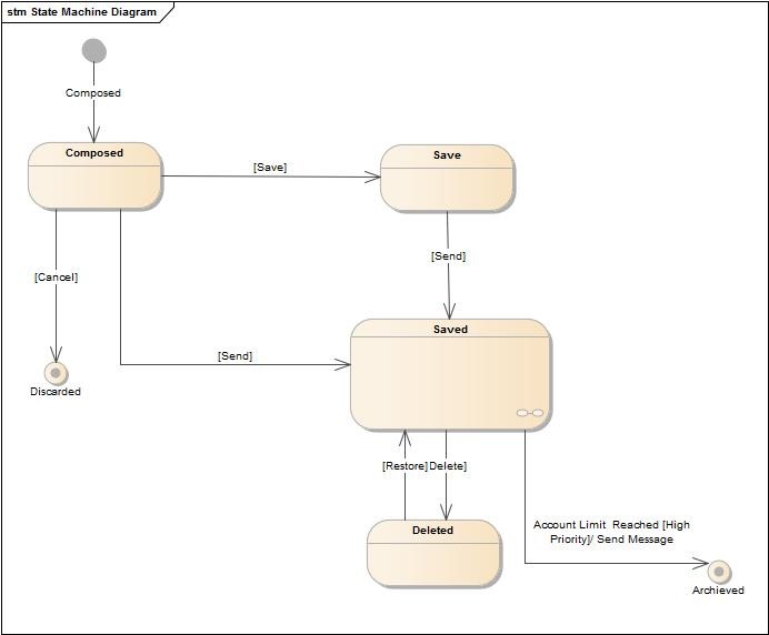

State machines were attractive to use as the states may also represent conditions that hold before or after the activities. This mapping of activity diagram features to state diagram were formalized in UML 1.x, leaving activity diagrams little more than the use of state machines to capture behavior and partially concurrent behavior within a work flow.ĭespite the (small) advantages of using UML 1.x activity diagram over state machines, such as the ability to cover the behaviors of collaborating elements, while state machines are limited to a single element, many modelers continued using state diagrams. In UML 1.x, an alternative to activity diagrams is the UML state machine diagram, in which states can be used to represent activities (namely the state of that activity being performed), and transitions represent the start or completion of activities. Additional changes allow the diagram to better support continuous behaviors and continuous data flows. In SysML the activity diagram has been extended to indicate flows among steps that convey physical matter (e.g., gasoline) or energy (e.g., torque, pressure). These changes cause many UML 1.x activity diagrams to be interpreted differently in UML 2.x ApplicationsĪn activity Diagram showing MESI protocol in a (>2 cores) processor.

While in UML 1.x, activity diagrams were a specialized form of state diagrams, in UML 2.x, the activity diagrams were reformalized to be based on Petri net-like semantics, increasing the scope of situations that can be modeled using activity diagrams. However, the join and split symbols in activity diagrams only resolve this for simple cases the meaning of the model is not clear when they are arbitrarily combined with decisions or loops. Typical flowchart techniques lack constructs for expressing concurrency. Hence they can be regarded as a form of flowchart. an encircled black circle represents the end ( final state).Īrrows run from the start towards the end and represent the order in which activities happen.


 0 kommentar(er)
